| ·Firm locking: separate the locking part from the detection part, re-examine the locking device, and greatly improve the retention and impact resistance when locking. ·Visualization: the large indicator light on the host computer will inform the opening and closing and locking state of the door, so you can also find the position where the door is not closed. ·Flexible installation: to realize a ruler with an aluminum frame of no more than 30 mm, and the main machine can be directly installed without a mounting frame. |
▊ | Product selection table |
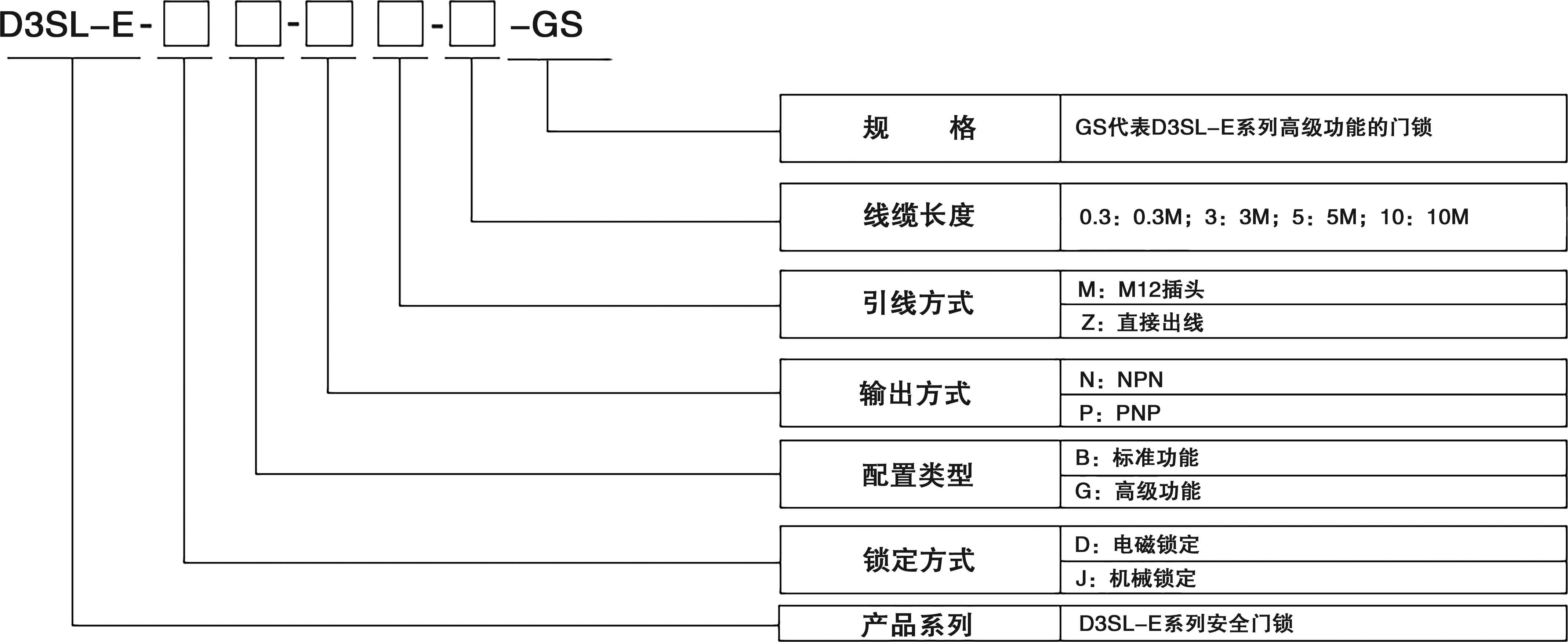
Locking mode | Configuration type | Output mode | Lead mode | Cable length | model |
Electromagnetic locking | normalized form | NPN | Direct outlet | 3M | D3SL-E-JB-N-Z3-GS |
5M | D3SL-E-JB-N-Z5-GS | ||||
10M | D3SL-E-JB-N-Z10-GS | ||||
M12 connector | / | D3SL-E-JB-N-M12-GS | |||
PNP | Direct outlet | 3M | D3SL-E-JB-P-Z3-GS | ||
5M | D3SL-E-JB-P-Z5-GS | ||||
10M | D3SL-E-JB-P-Z10-GS | ||||
M12 connector | / | D3SL-E-JB-P-M12-GS | |||
| High functional type | PNP | Direct outlet | 3M | D3SL-E-JG-P-Z3-GS | |
5M | D3SL-E-JG-P-Z5-GS | ||||
10M | D3SL-E-JG-P-Z10-GS | ||||
M12 connector | / | D3SL-E-JG-P-M12-GS |
▊ | Model description |
▊ | Fitting selection |
category | Product chart | name of an article | model |
Actuator | Universal coding actuator | DF-K2-GS | |
Code-only actuator | DF-K1-GS | ||
Mounting frame | 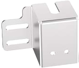 | Mounting bracket for rotating shaft (Applicable to hinged doors and hinged doors that open to the left) | D3SL-E-ZJ-JL-L |
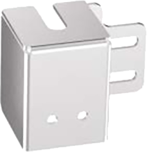 | Mounting frame for rotating shaft (Applicable to hinged doors and hinged doors that open to the right) | D3SL-E-ZJ-JL-R | |
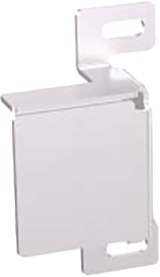 | Sliding mounting frame (Suitable for push-pull doors that open to the left) | D3SL-E-ZJ-TL-L | |
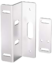 | Sliding mounting frame (Suitable for push-pull doors that open to the right) | D3SL-E-ZJ-TL-R | |
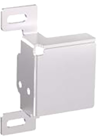 | Inner mounting bracket kit | D3SL-E-ZJ-NC | |
door handle Actuator bracket | Door handle actuator frame for right opening | D3SL-E--ZJ-DH-R | |
Door handle actuator bracket for left opening | D3SL-E-ZJ-DH-L | ||
M12 connecting line | Standard cable (8 pins and 8 cores) | D3SL-E-XL-P88C5 | |
D3SL-E-XL-P88C10 | |||
High functional cable (12 pins and 12 cores) | D3SL-E-XL-P1212C5 | ||
D3SL-E-XL-P1212C10 | |||
Note: The standard length of M12 connecting cable is 3m. If it needs 5m or 10m, please select the appropriate model according to the table. | |||
▊ | Safety latch |
Picture 2.png Safety Latch BS06 | RFID electromagnetic lock+safety latch |
|
|
▊ | technical parameter |
Locking type | Mechanical locking type | Electromagnetic locking type | |||||||
kind | normalized form | High function | normalized form | High function | |||||
cable specification | Terminal shape | Loose wire | M12 connector | Loose wire | M12 connector | ||||
Core number | 8 | 12 | 8 | 12 | |||||
length | 3m/5m/10m | 0.3m | 5m/10m | 0.3m | |||||
Output type | PNP/NPN | PNP | PNP/NPN | PNP | |||||
Response time (ms)※1※2 | Locking action | Lock → unlock | 220ms | 320 ms | |||||
Unlock → Lock | 220ms※3 | ||||||||
locking | Tensile strength (Fzh) | 2,000N more than | |||||||
Tolerance of insertion position deviation | ±2mm | ||||||||
Mechanical durability | More than 1 million times (door operation speed is 1 m/s) | ||||||||
Allowable operating frequency※ 4 | 1HZ | ||||||||
Allowable door radius | 250mm and above | ||||||||
Manual release ※5 | Front and back | ||||||||
Cascade connection | Up to 25 sets | ||||||||
Control output (OSS D output) | Output type | Transistor output ×2 | |||||||
Maximum load current | PNP:150mA and below, NPN:100mA and below. | ||||||||
Residual voltage (ON) | Maximum 2.5V (when the cable is 5m) | ||||||||
OFF voltage | Maximum 2.0V (when the cable is 5m) | ||||||||
leakage current | Up to 0.5mA | ||||||||
Maximum load capacity | 2.2μF | ||||||||
Load connection resistance | highest2.5Ω | ||||||||
AUX output (non-safety system output) | Output type | Transistor output | |||||
Output number | 1 | 2 | 1 | ||||
Maximum load current | 50mA | ||||||
Residual voltage (ON) | Maximum 2.5V (when the cable is 5m) | ||||||
External input (short circuit current) | Safety input | About 1.5mA×2 | |||||
Reset /EDM input | — | appointment10mA×1 | — | ||||
Lock control input | appointment2.5mA×1 | appointment2.5mA×2 | appointment2.5mA×1 | ||||
OSS D action switching input | — | ||||||
Power Supply | Power supply voltage | DC24V±20%Include ripple(P-P)10% Class2 | |||||
consumed power | 3.4W※8 | ||||||
protective circuit | Reverse connection protection of power supply, short circuit protection of outputs, surge protection of outputs and reverse connection protection of outputs. | ||||||
Environmental tolerance | Enclosure protection level | IP65/68 | |||||
Operating ambient temperature | -20℃ to +55℃ (no freezing) | ||||||
Storage ambient temperature | -25℃ to +70℃ (no freezing) ※9 | ||||||
Using ambient humidity | 5% to 95%RH | ||||||
Storage environment humidity | 5% to 95% RH | ||||||
Vibration resistance | 10 to 55Hz, double amplitude 2.0 mm, 5 minutes in each direction of X, Y and Z (IEC 60947-5-3). | ||||||
resistance to impact | 30GX, Y and Z directions 6 times (IEC 60947-5-3) | ||||||
Applicable specifications (safety) | EN61508、IEC 61508(SIL2/SIL3)EN 62061、IEC62061(SIL CL2/SIL CL3) ENISO 13849-1:2015(PLd、Category 2/PLe、Category 4) ENISO 14119(Type4)IEC 60947-5-3、EN 60947-5-3 UL61010-1、 CAN/CSA-C22.2 No.61010-1 | ||||||
texture of wood | Sensor host | shell | SUS304、Zinc alloy、PBT、PA66、NBR | ||||
Locking part | Aluminium alloy (hardening)、SUS304 | ||||||
electric cable | PVC | ||||||
key | shell | Zinc alloy、PBT、NBR | |||||
Locking part | SUS304、Zinc alloy | ||||||
▊ | Indicator light description |
LED status during normal operation | |||
functional mode | Indicator light | State description | |
Lock the door Normal output |
| Working status indicator: green light is on. OSSD output indicator: green light is on. INPUT input indicator: yellow light is on. LOCK lock indicator: green light is on. | 1. The detected key signal is normal. 2. The door closes when the key is detected to be in place. 3. The input signal is normal 4. Lock and output normally |
Unlock the door No output |
| Working status indicator: red light is on. OSSD output indicator: red light is on. INPUT input indicator: yellow light is on. LOCK lock indicator: off | 1. No key signal is detected. 2. The key was not detected in place and the door was opened. 3. The input signal is normal 4. No lock and no output |
The door is unlocked. Or lock the door. No output |
| Working status indicator: red light is on. OSSD output indicator: red light is on. INPUT input indicator: yellow light is on. LOCK lock indicator: the green light flashes at 1HZ. | 1. No key signal is detected. 2. Detect that the key is inserted in place and the door closes. 3. The input signal is normal 4. The door is not locked: the key signal was not detected when the door was just closed. Locking the door: No key signal was detected halfway after locking. There is no output in either case. |
Lock the door No output |
| Working status indicator: red light is on. OSSD output indicator: red light is on. INPUT input indicator: off LOCK lock indicator: green light is on. | 1. No input signal 2. Lock no output |
Lock the door No output |
| Working status indicator: red light is on. OSSD output indicator: red light is on. INPUT input indicator: yellow light flashes at 1HZ. LOCK lock indicator: green light is on. | 1. Wait for Rest reset signal 2. Lock no output |
OSSD mistake |
| Working status indicator: red light is on. OSSD output indicator: red light flashes 2HZ. INPUT input indicator: yellow light is on. LOCK lock indicator: green light is on. | 1.OSSD has a short circuit, or the wiring is incorrect. 2. Inductive load causes voltage surge of OSSD. 3.OSSD is affected by electrical interference. 4.OSSD has failed. 5. Lock no output |
EDM mistake |
| Working status indicator: red light is on. OSSD output indicator: red light flashes at 1HZ. INPUT input indicator: yellow light is on. LOCK lock indicator: green light is on. | 1.EDM input is not wired correctly. 2. Lock no output |
Locking exception |
| Working status indicator: red light is on. OSSD output indicator: red light is on. INPUT input indicator: yellow light is on. LOCK lock indicator: the green light flashes at 2HZ. | 1. Electromagnet error or optocoupler error. 2. Lock uncertainty, output |
hardware fault |
| Working status indicator: the red light flashes at 1HZ. OSSD output indicator: red light is on. INPUT input indicator: yellow light is on. LOCK lock indicator: green light is on. | 1. Internal fault detection error 2. Hardware failure 3. Lock no output |
▊Product dimension diagram
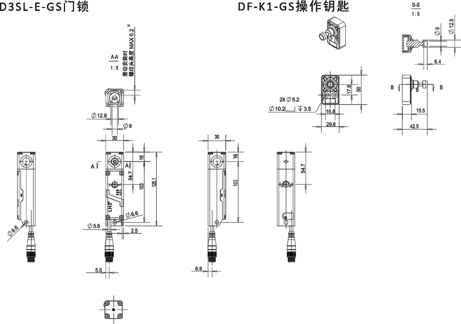
Note: For more details, please click the link below to download the information.

拉绳开关· 保护距离长达40米· 使用寿命长达2百万次· IP67防护等级· 设备有触动指示灯· 多触点可满足多种安装要求· 铝合金外壳耐撞击

·坚固锁定:将锁定部和检测部分离,重新审视锁定装置,大幅提高锁定时的保持⼒和耐冲击性·可视化:主机上的大型指示灯会告知门的开闭及锁定状态等,因此还能⻢上发现门未关的位置·安装灵活:实现不超过 30 mm铝框的⼩型尺⼨,主机可直接安装,无需安装⽀架▊产品选型表锁定......

通过电磁力500N轻松锁定安全门,防止门的松动及随意开启达到安全标准:PLe Category4 SIL3等级要求支持唯一编码不担心灰尘及异物的进入具备辅助输出

Lihong Safety Equipment Engineering (Shanghai) Co., Ltd.
E-Mail: info@lh-safety.com
Address: 581 Xiuchuan Road, Chuansha Town, Pudong New District, Shanghai
(Greenland East Coast International Plaza-Room A 313)
Copyright © Lihong Safety Equipment Engineering (Shanghai) Co., Ltd. ICP19034341-1 Technical Support: lanjujing