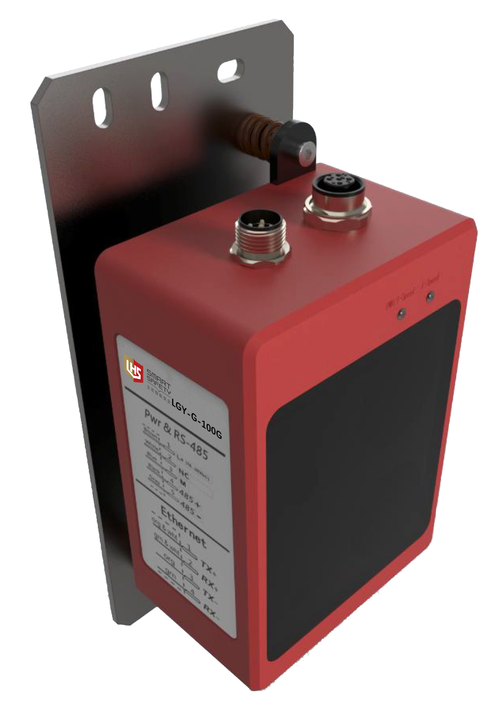
 | ·Red indicates that the light source can achieve rapid alignment. ·All-metal structural parts and all-glass lenses are adopted, which is extremely stable. ·Wide working temperature-40 ~+55. |
| ▊ | Product selection table |
working distance | type | transmission speed | joggle/interface | Working temperature | model |
0.2-100m | laser | 100 Mbit/s | Ethernet | -40℃...+55℃ | LGY-G-100G |
0.2-200m | LGY-G-200G | ||||
0.2-100m | LED | 10 Mbit/s | Ethernet | -40℃...+55℃ | LGY-G-100L |
0.2-200m | LGY-G-200L |
▊Industrial application
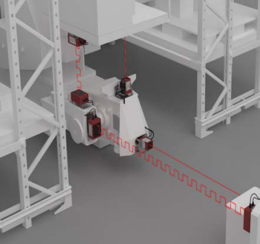 | 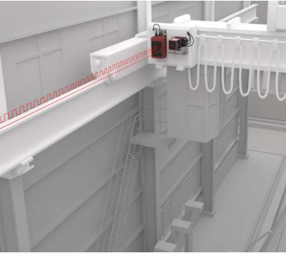 | 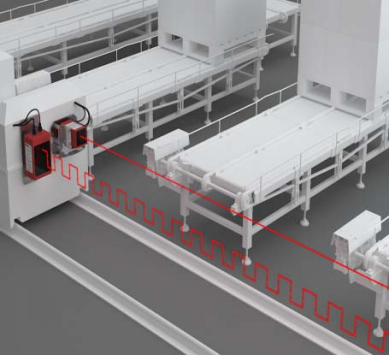 |
Industrial application of stacker | Application of crown block industry | RGV Industrial application |
▊technical parameter
performance parameter | ||
range | 100rice | 200rice |
Communication angle | ±1.2° | |
launcher | laser | |
receiver | photodiode | |
Laser spot | 25m@0.46m(oval) | |
100m@1.87m(oval) | ||
200m@3.74(oval) | ||
Indicating light source | Wavelength: 635nm | |
Laser grade | Secondary laser | |
IEC 60825-1:2014, EN 60825-1:2014 | ||
Laser lifetime | 100'000h @ 25℃ | |
Interface parameters | ||
EtherNET/IP | Network load level | II |
function | Measurement data output, parameter setting | |
Communication bandwidth | 10Mb/100Mbself-adaption | Optical port transmission bandwidth 100Mb/s |
RS-485 | Baud rate | 115200 |
data bit | 8 | |
Stop position | 1 | |
Check Digit | without | |
fluid control | without | |
function | Measurement data output, parameter setting | |
Mechanical/electronic parameters | ||
supply voltage | DC 18V…30V | |
power | < <10W (at 24VDC) | |
Initialization time | Typ. 5s | |
Connection type | A code 5-pin M12 plug | |
D-coded 4-pin M12 plug | ||
sheathing material | Aluminum die casting | |
the protection grades | IP65 | |
weight | 750g | |
Working temperature | -40℃…+55℃ | |
Storage temperature | -45℃…+85℃ | |
Electromagnetic compatibility (wireless) | EN 55032:2015,EN61000-3-2:2014,EN 61000-3-3:2013,EN 55035:2017 | |
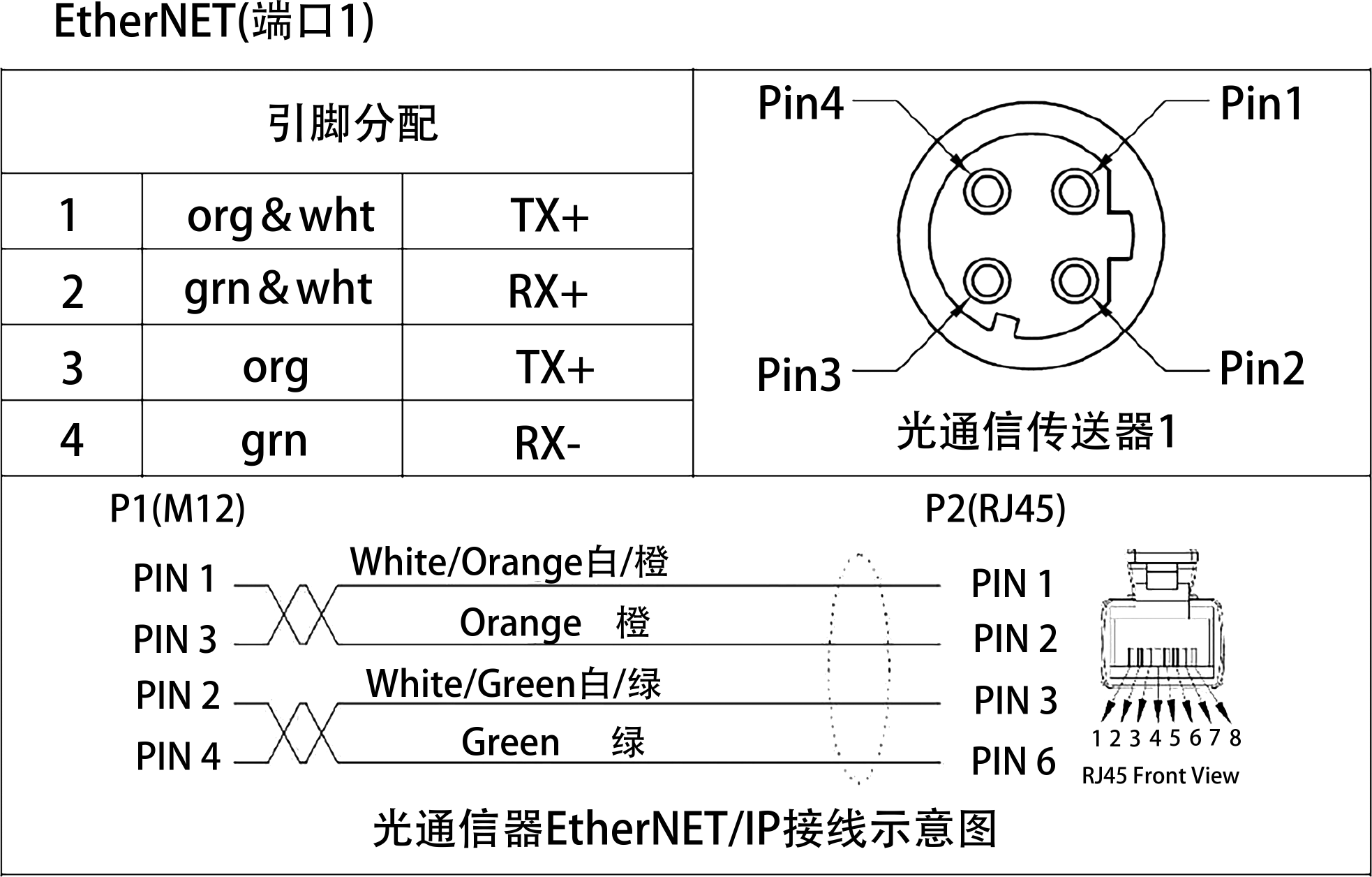
▊Schematic diagram of pin distribution and wiring
 |  |
▊Optical Communicator Indicator Description
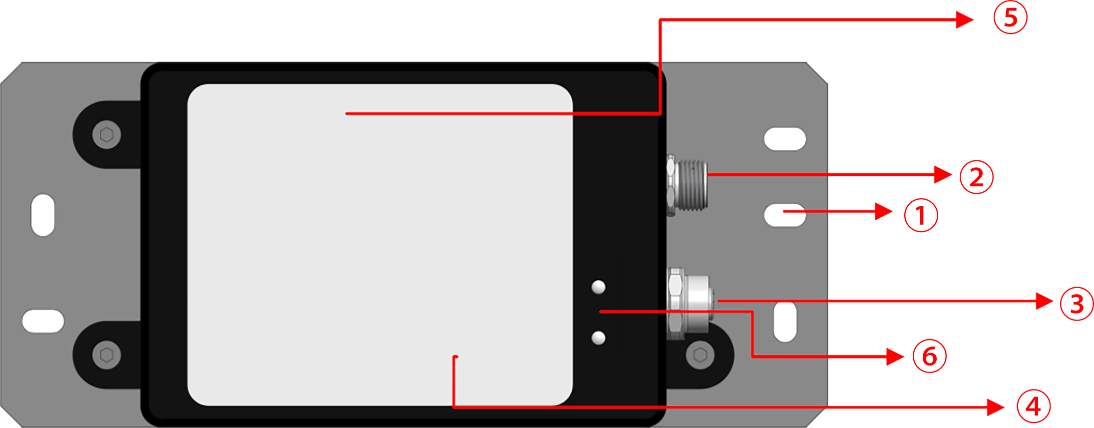 | ①Installing bottom plate ②Network port signal line; ③Power cord and RS485 interface (only used for factory debugging); ④Red laser light; ⑤Transmitting and receiving window; ⑥Indicator light; |
The indicator LED is displayed as described in the following table. |
Indicator light | condition | meaning |
PWR(red) | Changliang | Power on normally |
F-Link(green) | Always on/off | Related signal/dull signal |
F-speed(green) | Always on/flashing | Relevant signal/data transmission |
T-Link(green) | Always on/off | Network communication is normal/abnormal |
T-speed(green) | Always on/flashing | Network communication is normal/there is data transmission on the network. |
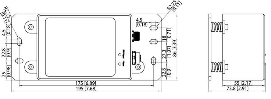
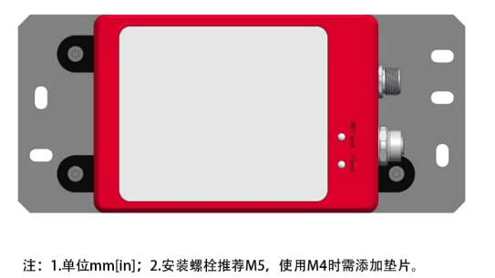
▊Product dimension diagram
 |  |
▊Installation example
This optical communication module can be installed vertically or horizontally, and the user can choose according to the actual situation. Here is an example of installing two optical communication modules horizontally. When installing two optical communicators (a pair), the outlet direction should be in the same direction and face up (down) or left (right) at the same time, as shown in the following figure. | 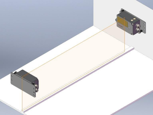 |
Copyright © 立宏安全设备工程(上海)有限公司 沪ICP备19034341号-1 技术支持:蓝巨鲸品牌推广